Cool Oil. Clean Fluid. No Aeration.
Hydraulic Reservoirs for Every Power Unit
Heavy-duty hydraulic reservoirs for stationary power units, mobile equipment, marine and offshore systems, and test stands. Sized and built so the oil runs cool, the pump never draws air, and contamination settles out instead of circulating.
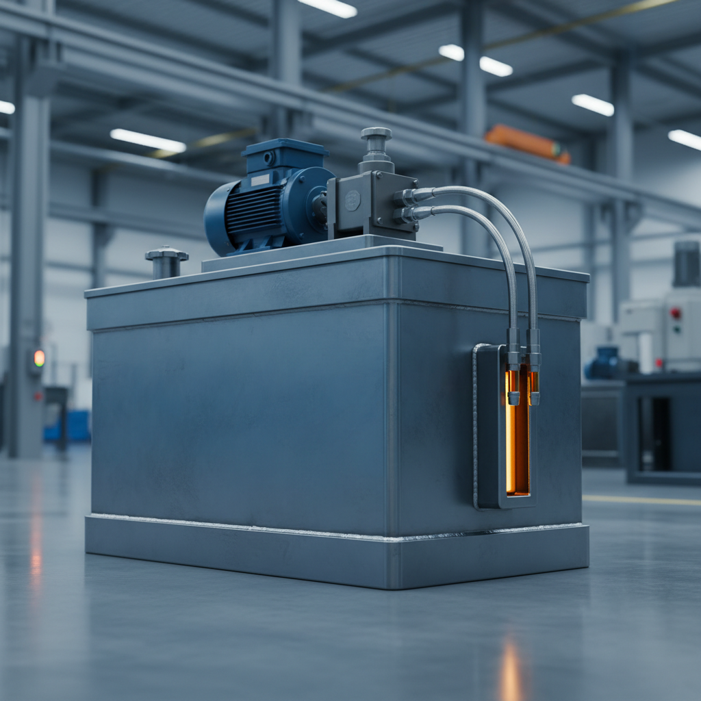
A note on terminology
Hydraulic reservoir, hydraulic oil tank and hydraulic fluid reservoir all describe the same component, and catalogues use them more or less interchangeably. “Reservoir” tends to dominate in fluid power engineering documentation, “tank” in shop-floor and mobile equipment usage. Where a distinction is drawn at all, it is that “reservoir” implies the full assembly including internals and accessories, while “tank” can mean just the fabricated vessel. This guide uses reservoir and tank interchangeably.
Fundamentals
What a hydraulic reservoir actually does
It is tempting to think of the reservoir as a container that happens to hold oil. It is closer to a conditioning vessel that also stores fluid. Four functions run in parallel inside it, and three of them depend on the fluid being still for long enough to do their work.
Fluid storage
The tank holds the working volume plus the swing volume. A single-rod cylinder returns more fluid than it takes on retraction and takes more than it returns on extension, so the level moves every cycle. The tank has to absorb that swing without uncovering the suction line at one extreme or overflowing the breather at the other.
Heat dissipation
Every pressure drop in a hydraulic circuit turns into heat, and on many systems the reservoir is the largest single cooling surface available. Tank walls radiate and convect heat to ambient air. When wall area alone cannot keep up with the heat the circuit generates, that is the signal to add a cooler rather than keep growing the tank.
Air separation
Return fluid arrives aerated, and entrained air is corrosive to system behaviour: it makes the fluid compressible, causes spongy actuator response, accelerates oxidation and drives dieseling damage. The tank's job is to hold the fluid still enough, and long enough, for those bubbles to rise and break at the surface before the pump draws the fluid again.
Settling and separation
Given a quiet zone and dwell time, heavier-than-oil contaminants drop out of the flow path. Particulate settles toward the floor and free water, being denser than most mineral oils, collects at the low point where a drain can remove it. Settling is a supplement to filtration, never a replacement for it.
Why dwell time is the number behind all of it
Air separation, settling and heat rejection are all governed by how long a given parcel of fluid stays in the tank between returning and being drawn back out. That residence time is a function of tank volume, flow rate and, critically, the path the fluid is forced to take once it is inside. Two tanks of identical volume can behave completely differently depending on whether the return line discharges into a baffled settling zone or straight at the suction strainer. Volume buys the opportunity for dwell time; internal geometry decides whether you actually get it.
Sizing
The three-times rule, and why it is argued about
The most widely repeated guidance in the field is that a reservoir should hold roughly three times the pump's per-minute flow. It is a useful first number and a poor final one. The ratio is a stand-in for dwell time, and it was calibrated on open industrial power units running mineral oil at modest power density.
Move outside those assumptions and it breaks in both directions. Mobile machines run far tighter ratios because there is nowhere to put a large tank, and carry a cooler instead. Some high-power stationary systems need more than three times to stay thermally stable. The defensible method is to treat the ratio as a starting point, then check it against a heat balance and the de-aeration time the fluid actually requires.
Read the full sizing section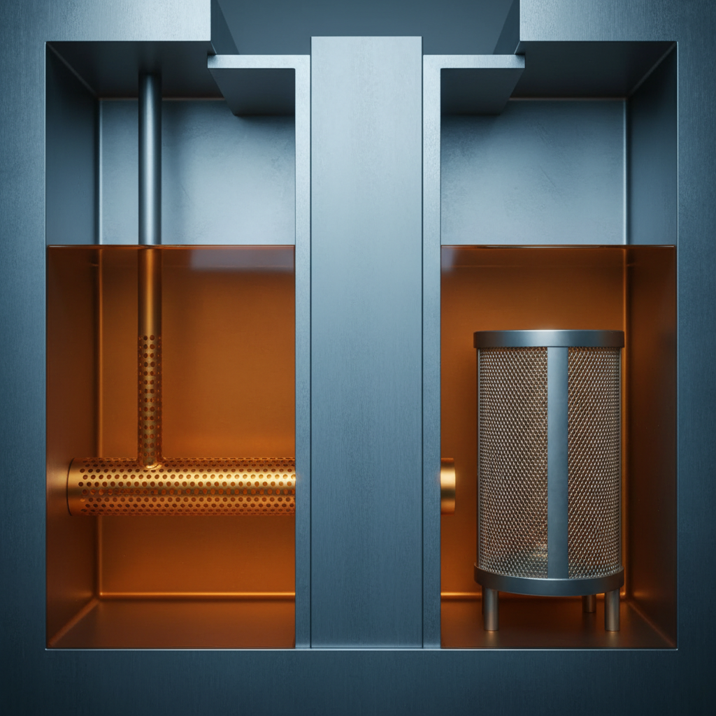
Configuration
How reservoirs are arranged
Most of the difference between reservoir styles comes down to one question: where does the pump sit relative to the fluid level? Getting a flooded suction is the single biggest favour a tank arrangement can do for pump life, and the named configurations are largely different answers to that problem under different space constraints.
L-shaped
The tank is stepped so the pump and motor sit on a lower platform beside a taller fluid column, flooding the pump inlet.
Overhead / JIC
The tank is raised on legs above the pump so the fluid level is always above the inlet, giving positive suction head by gravity.
Top-mount
The classic power unit: motor and pump bolt to the tank cover, with the suction line dropping into the fluid below.
In-frame
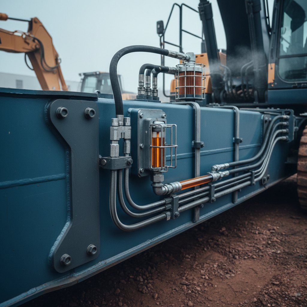
On mobile equipment the reservoir is built into the chassis or frame rail, trading a clean rectangular form for packaging space.
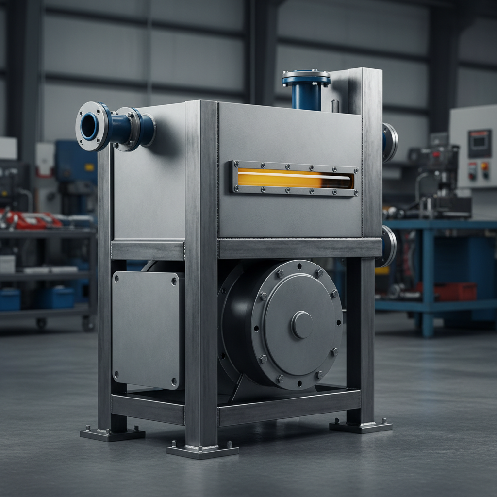
Stationary and mobile are different problems
A stationary power unit can usually be given the tank it wants. Floor space is negotiable, weight barely matters, and the tank can be sized generously enough to do most of the cooling on its own.
A mobile machine cannot. The reservoir competes with the operator cab, the engine, the fuel tank and the structure itself, so it ends up smaller, shaped around whatever volume is left, and often built into the frame. That forces the design in a predictable direction: a cooler becomes mandatory rather than optional, the internals have to work harder because dwell time is short, and everything that can be hit, splashed or buried in dust needs guarding.
Construction types and materialsWhat goes inside
The internals are what turn a volume of oil into a functioning conditioning vessel. Baffles create the settling and de-aeration zones. Diffusers slow returning fluid down so it stops stirring the tank. Suction strainers keep large debris out of the pump. Clean-out covers make the interior reachable. Magnetic plugs collect the ferrous wear debris that filtration alone tends to miss.
- Baffles and separator plates
- Return line diffusers
- Suction strainers and standoff height
- Clean-out and inspection covers
- Magnetic drain plugs
What bolts on
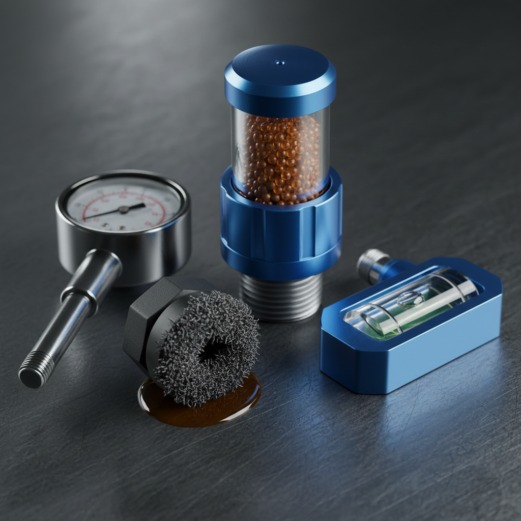
The accessories are where a reservoir stops being a passive vessel and becomes something you can monitor and control. They are also, routinely, where a well-designed tank is undone by a cheap component: an open vent in a dusty plant will contaminate a system faster than almost anything else on this list can protect it.
- Filler breathers and desiccant breathers
- Sight gauges and level / temperature indicators
- Temperature switches and level switches
- Immersion heaters
- Coolers and heat exchangers
Applications
Mobile and mounted installations
On mobile equipment the reservoir stops being a free-standing vessel and becomes part of the machine structure. That changes the failure modes more than it changes the physics.
- Sloshing and slope. A machine that pitches, rolls and brakes will move its fluid around. Baffles do double duty as slosh control, and the suction pickup has to stay submerged at the worst working angle the machine will see, not just on level ground.
- Vibration and fatigue. A frame-integrated tank carries structural load and road input at the same time. Weld detail at bracket and port penetrations is where cracking starts.
- Environment. Dust, mud, washdown and pressure washing all attack the breather and the fill point. This is the single most common ingress path on mobile machines and the easiest to design against.
- Thermal load. Small tank, high duty cycle and a hot engine bay mean the tank cannot be the primary cooling path. A cooler is part of the design rather than a remedy for one.
In service
Contamination control and fluid cleanliness
Most hydraulic component failures are traced back to fluid condition rather than to the component itself, and the reservoir is where fluid condition is either protected or lost. Cleanliness targets for hydraulic fluid are expressed using an ISO cleanliness code, a standardised way of reporting how many particles above given size thresholds are present in a sample.
The standard governs how the count is reported and how the code is constructed, so that a number from one lab means the same thing as a number from another. It does not tell you what your system needs. That target comes from the component manufacturers in the circuit, and in practice it is set by the most sensitive component you have, usually a servo or proportional valve or a high-pressure piston pump. Look it up for your equipment rather than assuming a figure.
Maintenance, draining and inspectionExclude
Keep contaminant out in the first place. A quality breather, sealed covers, clean top-up procedure and filtered fill are cheaper than any amount of downstream filtration.
Remove
Filter what gets in anyway. Pressure, return and offline filtration each solve a different part of the problem, and offline or kidney-loop filtration is the one that cleans the tank itself.
Monitor
Sample consistently from the same live point under the same conditions and trend the results. A single number tells you very little; the direction it moves tells you almost everything.
Questions
Frequently asked questions
What does a hydraulic reservoir do?
It does four jobs at once. It stores the fluid volume the circuit needs, including the swing volume from single-rod cylinders. It sheds heat through the tank walls, because in most systems the tank is the largest cooling surface available. It gives entrained air time to rise and release before the fluid is drawn back into the pump. And it lets water and heavy particulate settle out of the flow path so they can be drained rather than circulated. A tank that is treated as nothing but a bucket of oil tends to fail at the last three.
Why is the three-times-pump-flow sizing rule debated?
Because it is a proxy for the thing that actually matters. The ratio is a dwell-time heuristic that came out of open industrial power units running mineral oil at modest power density, and within that context it works. Outside it, it breaks in both directions: mobile machines routinely run far smaller ratios because there is no room for a large tank and a cooler carries the heat instead, while some high-power stationary systems need more. Use the ratio to get a first number, then verify it against a heat balance and the dwell time your fluid actually needs.
What is the purpose of a baffle inside the tank?
A baffle separates the return zone from the suction zone and forces returning fluid to travel a longer path before reaching the pump inlet. That extra travel buys the residence time that lets entrained air break out at the surface and heavy particles fall toward the floor. Without it, hot aerated return fluid can short-circuit straight across the tank to the suction line and go round again, which is one of the most common reasons a correctly sized tank still runs hot and foamy.
Should the reservoir be vented or sealed?
Most industrial reservoirs are vented through a filler breather, because the tank has to breathe as the level swings with cylinder movement and thermal expansion. The cost of breathing is that every inward breath draws ambient air carrying moisture and airborne dust, which is why the breather is a filtering or desiccant element rather than an open hole. Sealed, pressurized or bladder-isolated tanks are specified where the environment is severe or the fluid must not contact air at all, in exchange for added complexity and relief protection.
Where should the return line discharge?
Below the fluid surface, on the far side of the baffle from the suction line, and aimed so the flow is directed along a tank wall rather than straight at the suction strainer or straight up at the surface. Discharging above the surface splashes and aerates; discharging straight at the suction defeats the baffle. A diffuser on the end of the return line slows the fluid down and spreads it out, which is what makes the settling and de-aeration zones work as intended.
Why is there water in the hydraulic tank?
Usually condensation. A vented tank breathes humid ambient air as the fluid level and temperature swing, and when the tank cools overnight moisture condenses on the internal walls above the fluid line and runs down into the oil. Other sources are leaking heat exchanger cores, washdown ingress past a damaged cover seal, and contaminated top-up fluid. Free water at the tank low point can be drained; the harder problem is water in solution, which is why a desiccant breather and a controlled top-up procedure are the real fixes.
Can I just fit a bigger tank instead of a cooler?
Only up to a point, and it is usually the wrong lever. Tank cooling scales with surface area, which grows more slowly than the volume you are paying for, so each additional gallon buys less cooling than the last. A larger tank also raises fluid cost, fill time, weight and footprint. If a heat balance shows the circuit generates more heat than the tank surface can reject at the worst-case ambient, a heat exchanger is the correct answer and a bigger tank is a partial and expensive substitute.
What is a suction strainer and does every tank need one?
A suction strainer is a coarse mesh screen on the pump inlet inside the tank, there to keep large debris out of the pump. It is deliberately coarse because a fine element on the suction side risks starving the pump and causing cavitation, which does far more damage than the debris would. Not every system uses one: many designers prefer to leave the suction clear and control cleanliness with pressure and return line filtration plus a sealed, well-maintained tank, on the grounds that an unmonitored strainer that slowly blinds is a cavitation event waiting to happen.
Request a quote
Need a quote on a hydraulic reservoir?
Send the details of what you are building, replacing or troubleshooting and you will get a reply, usually within one business day. Useful things to include: pump flow and system pressure, fluid type, the duty cycle, the ambient environment, and the mounting arrangement you are constrained to.
General reference for engineering audiences. Sizing, materials and maintenance practice vary by application. Confirm against component manufacturers' specifications and the standards that apply to your system.