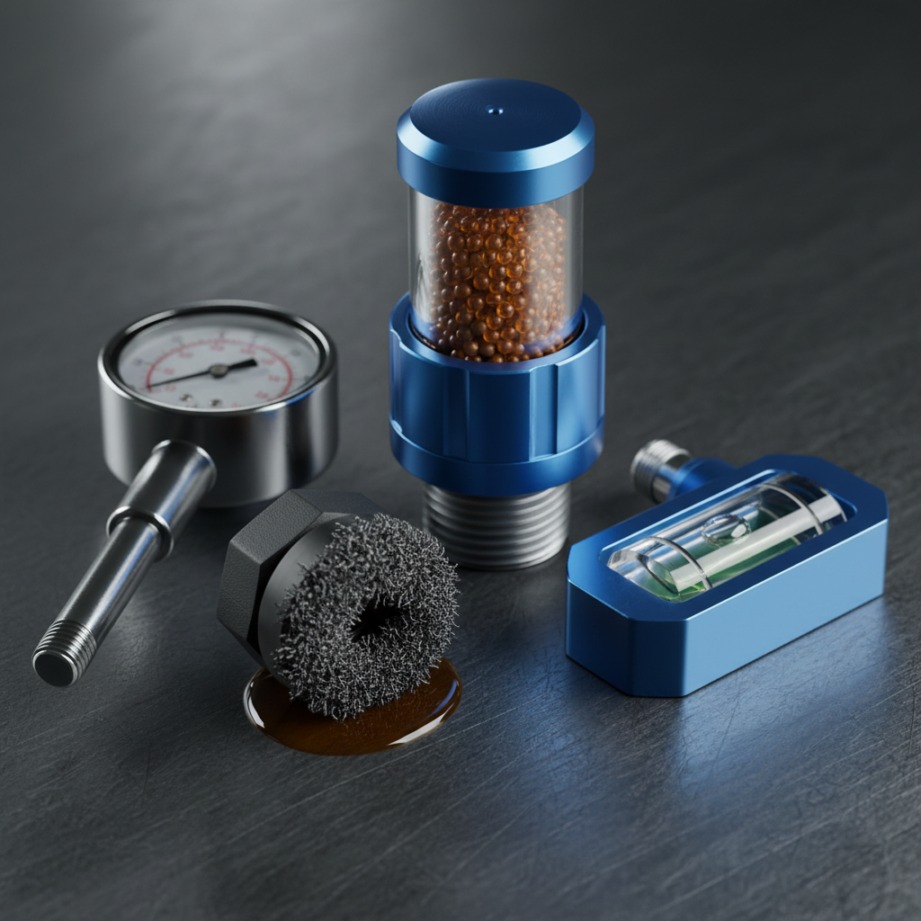
Of everything on this page, the breather deserves the most attention relative to its cost. A reservoir can be perfectly sized, properly baffled and built from the right material, and an open vent in a dusty plant will still fill it with airborne contaminant one breath at a time.
Filler breathers
A vented reservoir has to breathe. As cylinders extend and retract and as the fluid warms and cools, the air volume above the fluid changes, and air moves in and out through the breather. The filler breather usually combines that vent with the fill point, which is convenient and means one component guards the two largest ingress paths into the system.
The trap is treating it as a cap rather than as a filter. Every inward breath pulls in ambient air carrying airborne dust and water vapour, and a coarse or missing element makes the breather the dirtiest doorway in the whole installation. Match the element rating to the cleanliness the system needs and to the environment it sits in, and size the breather for the peak air flow the largest cylinder can demand, not for the tank volume.
In humid, dusty or washdown environments a desiccant breather adds a drying medium that strips moisture from incoming air. It is consumable, it changes colour as it saturates, and it is only doing anything if someone is actually replacing it. A saturated desiccant breather is just a restrictive vent.
Sight gauges and level indicators
A visual check of fluid level takes two seconds and catches leaks, overfilling and a slow loss that would otherwise show up as a cavitating pump. The common forms are a column-type sight gauge on the tank wall, a combined level and temperature gauge that puts both readings in one window, and a bayonet or dipstick-style indicator.
Specify the gauge so it spans the full working range including both swing extremes, and mark the correct static level clearly, because 'full' is meaningless unless it is defined at a stated condition. Position it where somebody can actually see it during normal operation rather than behind a guard.
On mobile equipment the gauge needs guarding against impact and against pressure washing, and it should be read on level ground at a defined machine attitude. A reading taken with the boom up on a slope is not comparable to one taken parked and level.
Temperature and level switches
Gauges tell a person who is looking. Switches tell the control system. A temperature switch or transmitter allows a high-temperature alarm or shutdown before the fluid degrades and seals suffer, and it is what drives cooler and fan control on systems where cooling is modulated.
A level switch protects the pump. Low level from a leak or from an unnoticed swing-volume excursion means air ingestion, and air ingestion damages a pump quickly. Interlocking a low-level switch to inhibit pump start is one of the cheapest pieces of protection available on a power unit.
Set points come from the fluid supplier's operating window and the component manufacturers' limits, not from a general rule. Take them from the data sheets for the fluid and equipment actually installed.
Immersion heaters
Cold fluid is thick fluid, and starting a pump against very high viscosity risks cavitation on the suction side and mechanical damage. In cold environments, or on machines left standing outdoors, an immersion heater brings the fluid to a viscosity the pump can actually draw before the system is allowed to start.
The specification trap is watt density. Concentrating heat into a small element surface can locally overheat the fluid film against the element and cook the oil, producing varnish and accelerated oxidation even though the bulk fluid temperature reads fine. Spread the load across adequate element area, keep the element fully submerged at the lowest level, and interlock it so it cannot energise dry.
Pair the heater with a thermostat and, ideally, a start interlock, so the machine will not run until the fluid is within its intended viscosity window rather than relying on an operator to wait.
Coolers and heat exchangers
When the heat balance shows the tank cannot reject what the circuit generates, a cooler is the correct answer. Air-blast coolers pass fluid through a finned core with a fan and suit mobile equipment and anywhere a water supply is impractical. Water-cooled shell-and-tube or plate exchangers are more compact for a given duty and are common on industrial units with process cooling water available.
Coolers are usually plumbed in the return line, so the fluid is cooled after it has done its work and before it re-enters the tank. That placement puts a heat exchanger core in the return path, which means its pressure drop has to be accounted for and it needs protection against cold-start pressure spikes.
The failure mode worth designing against on water-cooled units is internal core leakage, which puts cooling water directly into the hydraulic fluid. Water in oil is one of the more damaging contaminants there is, and a cooler core is a route by which it arrives in quantity rather than by condensation.
A short specification checklist
- Breather element rating matched to the system's cleanliness target and to the ambient environment, and sized for peak air flow from the largest cylinder rather than for tank volume.
- Desiccant breathers specified only where somebody owns the job of changing them.
- Sight gauge spanning both level extremes, clearly marked at a defined static condition, and visible without removing a guard.
- Temperature indication on every tank, and a switch or transmitter wherever an over-temperature event can go unnoticed.
- Low-level interlock on any unattended or automatically started power unit.
- Heater watt density kept low enough to avoid cooking the fluid film, with a dry-fire interlock.
- Cooler duty taken from the heat balance rather than from the size of the last one, with return line pressure drop accounted for.
- Every port and penetration reinforced, sealed and positioned so the accessory is reachable for service.
Ratings, set points and duty figures should be taken from the manufacturer data sheets for the components and fluid actually installed.