What an ISO cleanliness code governs
Hydraulic fluid cleanliness is reported using an ISO cleanliness code. The standard behind it defines a common method for counting the solid particles in a fluid sample above defined size thresholds and expressing the result as a short code, so that a result produced by one laboratory means the same thing as a result produced by another.
That is the whole of what the standard does: it standardises the measurement and the reporting. It does not tell you what your system needs. The target cleanliness for any given circuit comes from the manufacturers of the components in it, and in practice it is set by the most contamination-sensitive component installed, typically a servo or proportional valve or a high-pressure piston pump. Two systems with identical tanks can have very different targets for this reason.
Get the number from the source
Look up the required cleanliness code in the data sheets for the pumps and valves in your circuit, and the operating temperature and viscosity window in the fluid supplier's documentation. Codes and thresholds quoted from memory or copied from another machine are one of the more common ways a maintenance programme ends up targeting the wrong thing.
Exclude, remove, monitor
Contamination control breaks into three activities, and they are not interchangeable. Most programmes over-invest in the second and neglect the first and third.
Exclude
Keeping contaminant out is far cheaper than removing it later. That means a properly rated breather rather than an open vent, intact cover and gauge seals, capped ports and hose ends during any work on the system, and a disciplined top-up procedure. New fluid straight from the drum is routinely dirtier than the target cleanliness of the system it is going into, so filtering fluid on the way in is normal practice rather than an excess. The same applies at commissioning: a newly fabricated tank should be cleaned of weld spatter, scale and shop debris before it ever sees fluid.
Remove
Filtration handles what gets in anyway, and each position does a different job. Pressure filtration protects sensitive components immediately downstream. Return filtration catches wear debris before it re-enters the tank. Offline or kidney-loop filtration continuously circulates fluid from the reservoir through a filter and back, independently of the main circuit, which is the only arrangement that actively cleans the tank contents rather than just the flow passing through the system. On a tank with settled contamination, an offline loop or a filtration cart is the practical remedy.
Monitor
A single fluid analysis result is worth much less than a trend. To get a usable trend, sample the same way every time: from a dedicated live sampling point in the circuit rather than from the tank drain or through the filler cap, with the system at operating temperature and running, after flushing the sampling port. Sampling from a tank drain gives you a reading of the settled sludge at the low point, not of the fluid the system is circulating.
Sampling interval is a function of duty, environment and criticality, and the right reference is the fluid supplier's and OEM's guidance for that machine. Consistency matters more than frequency. Alongside laboratory analysis, the free indicators are worth reading at every service: what has collected on the magnetic drain plug, what the fluid looks and smells like, whether the level is holding, and what the temperature gauge reads under a known load.
Draining and clean-out
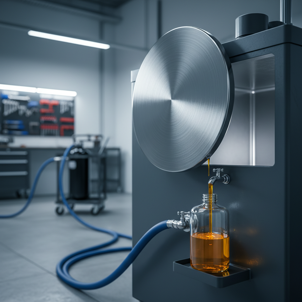
Draining free water and settled debris from the tank low point is a routine task, and it is most effective after the machine has stood long enough for settling to have happened rather than straight after a shift. It removes free water; it does nothing about water held in solution or emulsified in the fluid, which is why the breather and the cooler are the real controls there.
A full clean-out through the inspection cover happens at a much longer interval, normally at a scheduled shutdown alongside a fluid change. It is the only time anyone sees the inside of the tank, so it is worth doing properly and recording what was found.
What to look for once the cover is off
- Sludge and settled debris on the floor and in the corners, and how much of it there is compared with the last inspection.
- Varnish: a hard, tacky, often amber film on internal surfaces, indicating thermal or oxidative degradation of the fluid.
- Rust or blistered internal coating, particularly on the walls above the normal fluid line where condensation forms.
- Free water at the low point, and whether the floor actually drains toward it.
- Baffle condition and fixings, and any sign of a cracked or detached plate.
- The suction strainer: whether it is blinded, damaged, sitting in sludge, or missing entirely.
- Condition of the return diffuser and whether the return still discharges below the fluid line where it was designed to.
- Cover gasket and seal condition, since a poor reseal turns a maintenance task into a new ingress path.
Follow lockout, isolation, confined space and fluid handling procedures for your site. A drained reservoir can hold flammable vapour and is a confined space on larger systems.
Diagnosing common reservoir symptoms
Several familiar complaints point back to the tank, and most of them have a short list of likely causes worth working through in order.
Fluid runs hotter than it should
Look at: Heat generation exceeding what the tank can reject: relief valve dumping continuously, an undersized or fouled cooler, a blocked air-blast core, restricted airflow around the tank, or a duty cycle that has increased since the system was designed.
Foaming, or spongy actuator response
Look at: Air getting into the fluid and not getting out. Look for a return line discharging above the fluid surface, a return short-circuiting to the suction past a missing or damaged baffle, a suction-side air leak at a fitting or shaft seal, low fluid level, or dwell time lost to a stirred tank.
Noisy pump, cavitation
Look at: The pump is not getting a clean, full supply of fluid. Causes include a blinded suction strainer, low level uncovering the pickup, a suction line that is too long, too small or too restrictive, cold thick fluid at start-up, or air ingestion from any of the sources above.
Water in the tank
Look at: Usually condensation through a vented tank breathing humid air, which is why a desiccant breather is the standard fix. Also: a leaking water-cooled heat exchanger core, washdown or pressure-wash ingress past a damaged cover seal or gauge, and contaminated top-up fluid.
Rapid filter loading after a change
Look at: Something is generating or releasing contaminant rather than the filter simply doing its job. Consider settled debris disturbed inside the tank, a failing component shedding wear metal, degraded internal tank coating, or contaminant introduced with new fluid at the last top-up.
Varnish or sludge on internal surfaces
Look at: Thermal and oxidative degradation of the fluid. Look at sustained high bulk temperature, localised hot spots such as an over-dense immersion heater, air entrainment driving oxidation, water accelerating the process, and fluid that has simply been in service beyond its useful life.
The pattern worth remembering
When a tank runs hot, foams or keeps making water, the instinct is to look for a failed component. More often the cause is geometric or procedural: a return line moved during a repair and now discharging above the fluid line, a baffle that was never fitted, a breather nobody has changed, or a top-up done from an open drum. Those are cheap to fix and easy to miss, and they are worth eliminating before anything gets replaced.
Back to the reservoir fundamentals, or read the sizing section.