Configurations
A pump that has to lift fluid against gravity to prime is a pump working closer to cavitation than one fed by a flooded inlet. Most of the named reservoir configurations exist to give the pump a positive suction head under whatever space constraint the machine imposes.
L-shaped
The tank is stepped in profile so the pump and motor sit on a lower platform alongside a taller column of fluid. The result is a flooded pump inlet without raising the whole assembly, and a lower overall centre of gravity than an overhead arrangement. It costs more to fabricate than a plain box and takes more floor area for the same volume.
Typical use: Stationary power units where flooded suction matters and headroom is limited.
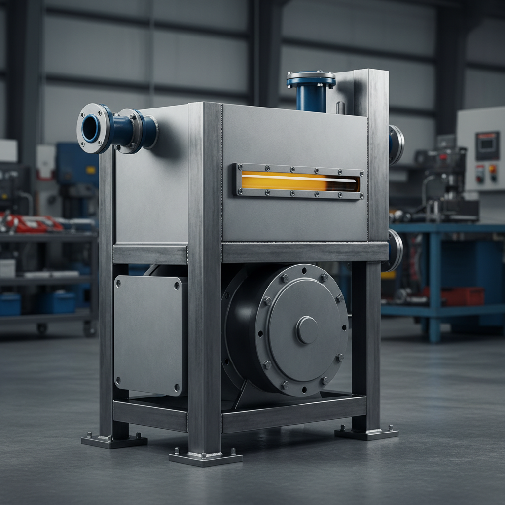
Overhead / JIC
The tank sits on legs above the pump, so the fluid level is above the inlet at all times and gravity does the priming. The style is closely associated with the classic JIC-form rectangular tank with a bolted, gasketed top cover and generous clean-out access. Easy to service, easy to drain completely, and it puts the mass up high.
Typical use: Test stands, filtration carts and industrial units where suction condition is the priority.
Top-mount
The most common industrial power unit form. The motor and pump bolt directly to the tank top cover and the suction line drops down into the fluid. Compact, cheap and self-contained, at the cost of a suction lift rather than a flooded inlet, and of transmitting pump and motor vibration and heat directly into the tank structure.
Typical use: General purpose stationary power units, presses, machine tools.
In-frame / integrated
On mobile machines the reservoir is built into the chassis, a frame rail or a structural member. It gives up the clean rectangular geometry and the easy service access in exchange for using volume that would otherwise be wasted. It also means the tank carries structural and fatigue load on top of its fluid duty.
Typical use: Excavators, loaders, tipper bodies, truck-mounted equipment.
Mobile versus stationary
The physics is identical; the constraints are not, and they push the design in opposite directions on almost every decision.
| Design driver | Stationary | Mobile |
|---|---|---|
| Volume | Generous, close to the classic ratio | Whatever the packaging leaves |
| Cooling | Often tank surface alone | Heat exchanger essentially mandatory |
| Shape | Rectangular, clean, serviceable | Follows the frame or the void |
| Weight | Largely irrelevant | A primary constraint |
| Orientation | Level and fixed | Pitches, rolls and brakes in service |
| Environment | Indoor, relatively clean | Dust, mud, washdown, wide temperature swing |
| Service access | Designed in | Fought for against everything else |
Materials
Material choice is a trade between cost, weight, corrosion resistance and thermal conductivity. Because a steel tank is doing real cooling work, moving to a material that conducts heat poorly is a thermal design decision as much as a corrosion one.
Carbon steel
Why it is used: The default. Strong, cheap, easy to weld and fabricate to any shape, and a good conductor, so it makes the tank an effective radiator.
Watch for: Bare interior surfaces rust where condensed water sits, and loose rust becomes circulating contaminant. Interior finish or coating and a good breather matter more here than in any other material.
Stainless steel
Why it is used: Corrosion resistance and a cleanable, non-shedding interior. Specified where the environment or the product is the driver rather than the hydraulics.
Watch for: Considerably more expensive, and a poorer conductor of heat than carbon steel, so a stainless tank rejects less heat for the same size.
Aluminium
Why it is used: Weight. On mobile and aerospace-adjacent equipment, saving mass on a large fluid vessel is worth real money.
Watch for: Lower strength than steel, more demanding to weld well, and susceptible to fatigue cracking at poorly detailed brackets and penetrations under vibration.
Polyethylene and polymers
Why it is used: Corrosion-proof, light, and cheap to mould in awkward shapes. Suits low-pressure, moderate-temperature duty and chemically aggressive environments.
Watch for: Poor thermal conductor, so the tank does very little cooling. Temperature limits and fluid compatibility both need checking against the specific resin and the specific fluid.
Internal features
This is where a tank earns its keep. Volume creates the opportunity for dwell time; the internals decide whether the fluid actually gets it.
Baffles and separator plates
A baffle is a plate that divides the tank so returning fluid cannot travel directly to the suction line. Forcing the flow around, under or over the plate lengthens the path, slows the fluid and creates a quiet zone where air can break out at the surface and particulate can fall. On mobile machines the same plates double as slosh control, keeping fluid over the suction pickup when the machine is working on a slope. Baffles also stiffen the tank structurally, which matters on large fabrications and on anything that vibrates.
Return line diffusers
Return flow arriving as a concentrated jet stirs the tank and defeats the settling zone. A diffuser spreads that flow out and drops its velocity before it enters the tank body. The return should discharge below the fluid surface, on the far side of the baffle from the suction, and be directed along a wall rather than at the suction strainer or up at the surface. Discharging above the surface aerates the fluid on every cycle, which is a common and easily corrected cause of foaming.
Suction strainers
A coarse mesh screen on the pump inlet, sized to stop large debris without restricting flow. It is deliberately coarse: a fine element on the suction side risks starving the pump, and cavitation damage is far worse than the debris would have been. The strainer needs standoff from the tank floor so it is not sitting in settled sludge, and it must stay submerged at the lowest working fluid level. Some designers omit it entirely and control cleanliness through pressure and return filtration instead, on the argument that an unmonitored strainer slowly blinding is itself a cavitation risk. Both positions are defensible; what is not defensible is fitting one and never inspecting it.
Clean-out and inspection covers
A bolted, gasketed opening large enough to actually reach the tank interior, ideally at both ends of a baffled tank so both zones are accessible. Without one, the inside of the reservoir is a place you can never inspect, never clean and never verify. Sludge, varnish, water and degraded internal coating are all invisible until someone opens the tank.
Drains and magnetic plugs
The tank floor should slope toward a low point so that water and settled debris collect somewhere a drain can remove them, rather than spreading across a flat bottom. A magnetic drain plug adds a passive collector for fine ferrous wear debris, and its real value is diagnostic: the quantity and character of what is clinging to it at each service is a direct signal about wear happening upstream, and it is one of the few condition indicators available without a lab.
Fabrication details worth specifying
- Continuous internal welds rather than stitch welds, so there are no crevices to trap contaminant and no unsealed pockets to hold water.
- An interior finish appropriate to the fluid and the material. On carbon steel this is what stands between condensed water and circulating rust.
- Reinforcement at every penetration and bracket. Ports, gauges and mounting feet are where fatigue cracks start on anything that vibrates.
- A tank floor that slopes to the drain point rather than sitting flat.
- Lifting provisions sized for the tank full, and mounting feet or pads that suit the surface it lands on.
- Thorough post-fabrication cleaning. Weld spatter, scale and shop debris left inside a new tank become the first contamination the system ever sees.